This development board, based on chipset NXP PCA9685, can be used to manage digital devices (including PWM control), such as LEDs, PWM fans and buzzers. This board can only be connected via I2C protocol, it has no USB type connections, so it must be used with a development board with a USB interface, for example a board based on the FTDI FT232H chipset. For ease we are going to connect it to the FTDI FT232H device, of which there is a dedicated page on this site - refer to the above page for installation.
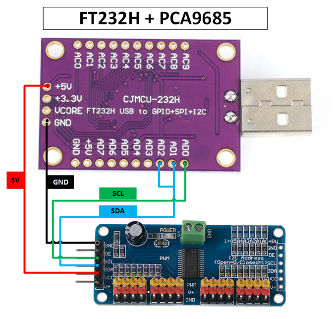
This development board must be connected to the FTDI FT232H development board via I2C protocol. The connection connectors are listed below:
| Image | Board FT232H | Board PCA9685 |
|---|---|---|
|
AD0 | SCL |
| AD1 + AD2 | SDA | |
| +5V / +3.3V | VCC | |
| GND | GND |
The "V+" connector of the PCA9685 card is optional, and is used to power all the red "V+"
connectors of the 16 Input/Output ports. Another way to power the red "V+" connectors of these 16 ports is to use the large green power connector at the
top of the PCA9685 board. The voltage of these "V+" connectors is not managed by the PCA9685 board, therefore it is possible to power these
red connectors with voltages even higher than 5 Volts. Be very careful not to connect the "VCC" pin of the PCA9685
board to a voltage higher than 5 Volts, to avoid damaging the entire PCA9685 board (the "VCC" pin is only used to power the internal circuits of
the PCA9685 board, not to power the whole block of Input/Output connectors).
The "OE" (Output Enable) connector of the PCA9685 card is optional, and is used only to enable/disable all pins of the card's Input/Output ports.
Physically connecting it to the FTDI FT232H card is feasible, but it is useless, considering that the activation/deactivation of the pins can also be
done via software.
The default hexadecimal address of the PCA9685 card is "40", but it can be changed by shorting the A0-A5 jumpers with a solder. These
jumpers must be considered as a binary number, A0 is bit 0, while A5 is bit 5, the result of these bits must be added to the hexadecimal number "40".
Therefore if only jumper A0 is short-circuited, the I2C address will become "41" ("hex 40" + "bin 00001" = "hex 41"), while if only jumper A5
is short-circuited, the I2C address will become "50" ("hex 40" + "bin 10000" = "hex 50").
To get the hexadecimal address of this card, go to the PyFTDI website and download the following Python script.
Once downloaded, run it via the Python interpreter. The output of the above script is as follows:
admin@RT-AC86U:/# python3 i2cscan.py

   0 1 2 3 4 5 6 7 8 9 A B C D E F
0: W . . . . . . . . . . . . . . .
1: . . . . . . . . . . . . . . . .
2: . . . . . . . . . . . . . . . .
3: . . . . . . . . . . . . . . . .
4: W . . . . . . . . . . . . . . .
5: . . . . . . . . . . . . . . . .
6: . . . . . . . . . . . . . . . .
7: W . . . . . . . .
To manage the PCA9685 board, we can use one of the following Python libreries: