This development board, based on chipset TI ADS1115, is a 16-bit Analog-to-Digital Converter with 4 input channels and I2C compatible serial interface. This board can only be connected via I2C protocol, it has no USB type connections, so it must be used with a development board with a USB interface, for example a board based on the FTDI FT232H chipset. For ease we are going to connect it to the FTDI FT232H device, of which there is a dedicated page on this site - refer to the above page for installation.
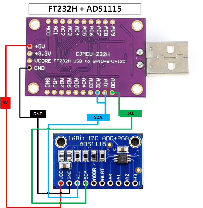
This development board must be connected to the FTDI FT232H development board via I2C protocol. The connection connectors are listed below:
| Image | Board FT232H | Board ADS1115 |
|---|---|---|
|
AD0 | SCL |
| AD1 + AD2 | SDA | |
| +5V / +3.3V | VDD | |
| GND | GND |
The default hexadecimal address of the ADS1115 card is "48", but you can change it using the ADDR pin. This pin can be connected to the GND, VDD, SDA and SCL pins, obtaining 4 different addresses, as shown in the following table:
| ADDR pin connection | Hexadecimal address |
|---|---|
| GND | 48 |
| VDD | 49 |
| SDA | 4A |
| SCL | 4B |
To get the hexadecimal address of this card, go to the PyFTDI website and download the following Python script. Once downloaded, run it via the Python interpreter. The output of the above script is as follows:
admin@RT-AC86U:/# python3 i2cscan.py

   0 1 2 3 4 5 6 7 8 9 A B C D E F
0: . . . . . . . . . . . . . . . .
1: . . . . . . . . . . . . . . . .
2: . . . . . . . . . . . . . . . .
3: . . . . . . . . . . . . . . . .
4: . . . . . . . . W . . . . . . .
5: . . . . . . . . . . . . . . . .
6: . . . . . . . . . . . . . . . .
7: . . . . . . . . .
To manage the ADS1115 board, we can use one of the following Python libreries: