This development board, based on chipset MTI MCP4725, is a single channel, 12-bit, voltage output Digital-to-Analog Converter with integrated EEPROM and an I2C compatible serial interface. This board can only be connected via I2C protocol, it has no USB type connections, so it must be used with a development board with a USB interface, for example a board based on the FTDI FT232H chipset. For ease we are going to connect it to the FTDI FT232H device, of which there is a dedicated page on this site - refer to the above page for installation.
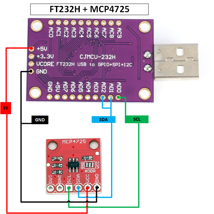
This development board must be connected to the FTDI FT232H development board via I2C protocol. The connection connectors are listed below:
| Image | Board FT232H | Board MCP4725 |
|---|---|---|
|
AD0 | SCL |
| AD1 + AD2 | SDA | |
| +5V / +3.3V | VCC | |
| GND | GND |
The default hexadecimal address of the MCP4725 card is "60", but you can change it on the printed circuit board in the
ADDR position, unsoldering the jumper created on the GND side and soldering the jumper on the VCC side. This changes the hexadecimal address to "61", so only two of these development boards can be connected to the
FTDI FT232H development board.
To get the hexadecimal address of this card, go to the PyFTDI website and download the following Python script.
Once downloaded, run it via the Python interpreter. The output of the above script is as follows:
admin@RT-AC86U:/# python3 i2cscan.py

   0 1 2 3 4 5 6 7 8 9 A B C D E F
0: . . . . . . . . . . . . . . . .
1: . . . . . . . . . . . . . . . .
2: . . . . . . . . . . . . . . . .
3: . . . . . . . . . . . . . . . .
4: . . . . . . . . . . . . . . . .
5: . . . . . . . . . . . . . . . .
6: W . . . . . . . . . . . . . . .
7: . . . . . . . . .
To manage the MCP4725 board, we can use one of the following Python libreries: